Wet Etching & Cleaning Baths
Wet etching and cleaning baths in the electronics and semiconductor industry are multi‑stage chemical treatments that use acidic or alkaline solutions to remove native oxides, photoresist residues, and metallic contaminants from silicon wafers and other micro‑fabricated components. These baths are purpose‑built to dissolve or undercut specific materials so that subsequent lithography, doping or deposition steps achieve precise pattern geometry. The chemical mixtures may be rich in hydrofluoric acid, nitric acid, phosphoric acid, potassium hydroxide, sodium hydroxide, or surfactants depending on whether the goal is oxide removal, texturization or particle cleaning. Bath chemistry is typically controlled at tight concentrations to achieve consistent etch rates, and processors rely on ultrapure make‑up water to dilute commercial reagents and rinse wafers between steps. In plain language, wet etching & cleaning baths are controlled chemical tanks that dissolve unwanted layers and contaminants from semiconductor surfaces using carefully balanced acids or bases. Operators rely on recirculating pumps, heaters and fume exhausts to keep the solution homogeneous and safe, while robotics handle wafer cassettes to avoid manual contact with aggressive chemicals.
Process engineers value these baths because they allow high throughput surface preparation with relatively simple equipment compared to plasma dry etching. When properly tuned, wet etching yields smooth sidewalls, low surface roughness and minimal particle defects, which translates into better device performance and manufacturing yield. However, the business value depends on water quality because any ionic impurity introduced during dilution or rinsing can change the etch rate, cause pitting or deposit metallic residues on clean surfaces. Excess fluoride or nitrate from depleted solutions also generates hazardous wastewater that must be neutralized and filtered before discharge. To protect product and the environment, water treatment systems supply ion‑free make‑up water, monitor bath parameters such as conductivity and pH, and treat spent solutions with chemical precipitation, membrane filtration and sludge dewatering before recycling or disposal. Quality risks include cross‑contamination between acid and base baths, scaling on tank walls from precipitated fluorides, and corrosion of sensors if they are not constructed of appropriate materials. Therefore integrated water management is an inseparable part of wet etching and cleaning operations.
Related Products for Wet Etching & Cleaning Baths
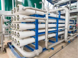
Reverse Osmosis
Reverse Osmosis (RO) and Electrodeionization (EDI) use semipermeable membranes and electric fields to reject salts, silica, and organics from municipal supply. They provide a low‑conductivity feed to the DI units and reduce total dissolved solids to below 1 mg/L.
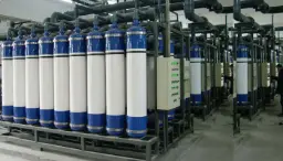
Ultrafiltration
Ultrafiltration units suspended solids and colloidal silica from rinse water and treated effluents. Polymeric or ceramic membranes with pore sizes in the micrometer range retain precipitated sludge while allowing clear water to pass.
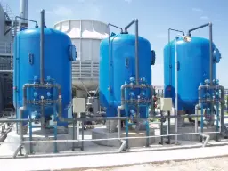
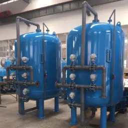
Activated Carbon Filters
Activated carbon beds remove organic contaminants and trace surfactants from rinse waters. By breaking down organics to carbon dioxide, these systems prevent bacterial growth and maintain low total organic carbon (TOC).
Deionization
Mixed‑Bed deionization (DI) units remove dissolved ions through cation and anion exchange resins to achieve resistivity above 15–18 MΩ·cm for make‑up water. Automatic regenerations ensure consistent quality, and polishing cartridges are often deployed before the baths.
These systems are critical to wet etching because chemical purity directly affects etch rate consistency, surface morphology and overall yield. The DI‑RO‑EDI train produces ultrapure water that will not contribute metallic ions or silica to the bath, ensuring that acid and base concentrations remain the dominant variables. Neutralization and precipitation reactors protect downstream sewer infrastructure and comply with effluent regulations by removing fluoride and metals from spent baths before discharge. Filtration steps capture particulate matter that would otherwise scratch wafers or clog spray nozzles. Dewatering equipment manages the solid waste generated during precipitation and reduces disposal volumes. UV oxidation and activated carbon adsorption maintain low organic load and microbial control, which is essential because organic residues can slow etching or promote photoresist adhesion failure. Finally, inline instrumentation closes the feedback loop by providing real‑time data on conductivity, resistivity, pH, and fluoride levels so that operators can make timely adjustments without interrupting production.
Key Water‑Quality Parameters Monitored
Precise control of water quality underpins the success of wet etching and cleaning baths. Electrical conductivity or its inverse, resistivity, serves as a real‑time indicator of ionic content in make‑up water and rinse water. Ultrapure water used to dilute acids typically has a resistivity in the 18.2 MΩ·cm range, which corresponds to a conductivity around 0.055 µS/cm. As rinse water encounters etchant residues, its conductivity rises; online sensors detect values above 1–2 µS/cm to trigger bath replacement or cascade to another rinse stage. pH measurement is equally important; acid baths may operate at pH 1–3, while alkaline texturing baths can reach pH 11–13. Rinse tanks and treated effluent should have near‑neutral pH (6.5–8.5) to protect downstream equipment and comply with discharge permits. Fluoride concentration is closely watched because hydrofluoric acid attacks silica. Fresh HF baths contain tens of grams per liter of fluoride; wastewaters after neutralization typically need fluoride reduced to below 15 mg/L before discharge. Operators monitor nitrate levels in nitric acid etch solutions and spent streams; nitrates can exceed 1 000 mg/L in spent baths and must be reduced to less than 30–50 mg/L in final effluent through biological denitrification or ion exchange.
Metal ions such as copper, iron, aluminum and chromium arise from etching metallic films or from corrosion of process equipment. Even microgram per liter levels of these metals in make‑up water can deposit on wafer surfaces and affect device performance. Waste streams may contain milligram per liter concentrations that require precipitation and filtration. Silica is another key parameter because it can precipitate in alkaline solutions and deposit on wafer surfaces or membrane elements; typical limits for make‑up water are below 50 µg/L. Total organic carbon (TOC) in rinse water should be kept below 500 µg/L because organics can adsorb onto wafer surfaces and affect cleaning efficiency. Dissolved oxygen and oxidation‑reduction potential (ORP) monitoring are important when hydrogen peroxide or other oxidants are used as additives; these parameters inform the safe handling of oxidants and the potential for radical reactions that could damage wafers. Temperature control is also critical; etch rates roughly double for every 10 °C increase, so typical bath temperatures are maintained within ±1 °C of target values that vary from 20 °C for HF oxide removal to 80 °C for alkaline texturization. Proper monitoring ensures that processes remain within tight specifications and that water treatment systems can respond promptly to deviations.
| Parameter | Typical Range | Control Method |
| Resistivity / Conductivity | Make‑up water >15 MΩ·cm (0.07 µS/cm); rinse water replacement threshold 1–2 µS/cm | Continuous inline conductivity sensors; mixed‑bed DI polishing |
| pH | Acid baths 1–3; alkaline baths 11–13; effluent 6.5–8.5 | pH probes with HF‑resistant glass; automatic acid or base dosing |
| Fluoride Concentration | Fresh HF bath tens of g/L; post‑neutralization effluent <15 mg/L | Ion‑selective electrodes; lime or CaCl₂ precipitation and filtration |
| Nitrate/Nitrite | Spent baths 500–1 000 mg/L; treated effluent <30 mg/L | Ion chromatography or UV absorbance; biological denitrification or ion exchange |
| Metal Ions (Fe, Cu, Al) | Make‑up water <0.05 mg/L; spent baths 5–50 mg/L | ICP‑OES or colorimetric sensors; hydroxide precipitation and membrane filtration |
| Silica | Make‑up water <50 µg/L; high levels can cause scaling | Silica analyzers; RO and ion exchange |
| Total Organic Carbon (TOC) | Make‑up water <500 µg/L; rinse water replacement threshold 1 000 µg/L | UV oxidation and TOC analyzers; activated carbon |
| Dissolved Oxygen / ORP | Dependent on oxidant dosing; monitor to prevent over‑oxidation | ORP probes; controlled peroxide or ozone dosing |
| Temperature | Acid baths ~20–30 °C; alkaline baths ~70–80 °C; rinse water ~25 °C | Inline thermocouples; heat exchangers and heaters |
Design & Implementation Considerations
Successful integration of wet etching and cleaning baths with water treatment systems requires careful design that accounts for process chemistry, throughput and regulatory constraints. Facilities must balance high production volumes with the stability of chemical baths; a typical acid texturing bath may operate for 80 hours before replacement, during which time the consumption of hydrofluoric and nitric acid can exceed ten times the original charge. Designers must estimate consumption rates and incorporate buffer tanks, chemical dosing equipment and sensors to maintain consistent concentrations without manual intervention. Material selection is critical because hydrofluoric acid attacks glass and many metals; process tanks, piping and sensor housings are commonly fabricated from high‑density polyethylene (HDPE), perfluoroalkoxy (PFA) resin, or polytetrafluoroethylene (PTFE). When alkaline mixtures contain potassium hydroxide or sodium hydroxide, they attack certain elastomers, so gaskets and seals must be chosen accordingly. Floor drainage and secondary containment must be designed to capture spills and prevent mixing of incompatible chemicals. The plant layout should provide segregated acid and base wet benches with dedicated exhaust systems to prevent cross‑contamination and maintain worker safety. Local regulations may require bunded areas, emergency showers and eye wash stations near chemical handling points.
Alignment with industry standards and guidelines ensures that the equipment meets quality and safety expectations. Specifications such as SEMI F57 for ultraclean polypropylene piping, SEMI S2 for environmental, health and safety evaluation of semiconductor manufacturing equipment, and ISO 14644 for cleanroom cleanliness influence material selection and construction details. Designers must also consider national effluent standards that limit discharge of fluoride, nitrate, heavy metals and suspended solids; these drive the sizing of neutralization tanks, precipitation reactors and filter presses. A robust control system integrates pH controllers, conductivity meters, flow sensors and programmable logic controllers (PLCs) to regulate chemical dosing, monitor tank levels and manage alarms. Interlocks and emergency shutoff systems protect operators by preventing acid addition when there is insufficient rinse water or when exhaust fans fail. Simultaneously, automation increases repeatability and reduces operator exposure. Implementation should include redundancy for critical components like pumps and sensors because unscheduled downtime of a wet bench can idle an entire fabrication line. Commissioning procedures involve water quality testing, instrument calibration and wet runs with surrogate chemicals to verify that the system responds correctly under different scenarios. Once operational, the design must allow for expansion or modification as product volumes change, new chemistries are introduced or regulatory limits tighten.
A process diagram illustrating bath conductivity over time may help operators understand when to replace or replenish the etch solution. Below is a conceptual placeholder for such a graph.
Operation & Maintenance
Operation of wet etching and cleaning baths hinges on disciplined procedures and continuous monitoring. Before starting a production batch, operators verify that make‑up water resistivity exceeds the required threshold by checking inline meters. The acid or base solutions are charged to the tank using pre‑mixed concentrates diluted with ultrapure water; mixing occurs under recirculation to ensure homogeneity. Wafer cassettes are loaded into carriers that move between process baths under the control of robotics, minimizing splash and vapor release. During operation, conductivity and pH sensors send signals to chemical dosing pumps that add acid or base to compensate for consumption. If the acid concentration drifts, an automatic reagent addition corrects the bath within minutes. Rinse tanks are operated in a cascading configuration where the cleanest water is in the last stage and flows countercurrent to the wafers; sensors trigger replacement when conductivity exceeds setpoints or after a weekly time‑based schedule. Periodic sampling of fluoride and metal concentrations is performed using ion‑selective electrodes or inductively coupled plasma analysis to verify that process control remains within specification.
Maintenance practices must anticipate the harsh conditions of these baths. pH probes immersed in acidic or alkaline solutions are cleaned and recalibrated at weekly intervals to prevent drift; HF‑resistant glass or antimony electrodes are used in HF baths but still require inspection for coating by calcium fluoride precipitates. Conductivity sensors are periodically flushed with dilute hydrochloric acid to remove scaling. Filters in the microfiltration units are backwashed or replaced according to pressure drop alarms or after monthly operating hours to avoid breakthrough of precipitated solids. Membrane elements in RO and EDI systems are cleaned in place with low‑concentration caustic or acid solutions and replaced every two years on average depending on fouling. Neutralization tanks are inspected for sludge accumulation, and stirrers are checked for wear. Sludge from precipitation processes is dewatered with filter presses; filter cloths are replaced when they no longer dewater efficiently. The dewatering cake is analyzed for fluoride and heavy metal content before disposal. Preventive maintenance schedules include quarterly checks on pump seals and bearings, inspection of heat exchanger fins, and verification of chemical feed lines for leaks. Documentation of setpoints such as pH 7.0 ± 0.5, conductivity 1.0 µS/cm or fluoride 10 mg/L ensures that new operators understand operational limits. Regular training of staff on chemical handling, personal protective equipment and emergency response is essential because accidents can have severe health implications.
A simple mass balance calculation illustrates dosing requirements for fluoride removal. For instance, to treat 2 000 L of wastewater containing 50 mg/L of fluoride, the fluoride mass is 100 g. Based on the stoichiometry of the precipitation reaction CaCl₂ + 2F⁻ → CaF₂ + 2Cl⁻ (molar mass CaCl₂ = 111 g/mol and F⁻ = 19 g/mol), a single dose of calcium chloride required to precipitate this fluoride is 292 g CaCl₂.
Challenges & Solutions
Process engineers encounter many practical challenges in wet etching and cleaning operations that revolve around maintaining consistency, extending bath life and meeting environmental regulations. Problem: Uncontrolled consumption of acid or base leads to fluctuating etch rates, non‑uniform patterns and excessive chemical costs. Solution: Installing inline titration or conductivity control systems coupled with precision dosing pumps stabilizes bath composition and allows operators to adjust addition rates based on real‑time feedback rather than fixed recipes. Another common issue is scaling and sludge formation in neutralization tanks and pipework. Problem: When fluoride or metal precipitation reactions are not well controlled, insoluble salts coat sensors, pumps and tank walls, reducing system capacity and causing sensor failures. Solution: Optimizing the order of chemical addition, maintaining proper pH ranges and implementing periodic acid cleaning of pipework prevents excessive scaling. Introducing flocculants can also agglomerate fine precipitates for easier filtration.
Corrosion is a persistent challenge because hydrofluoric acid and strong bases attack metals, glass and even some plastics. Problem: Inadequate material selection causes leaks or component failures that result in unplanned downtime and safety incidents. Solution: Specifying PFA‑lined piping, PTFE valves and HF‑resistant pH electrodes mitigates corrosion risks. Periodic inspection and non‑destructive testing ensure that hidden corrosion is detected before catastrophic failure. Variability in make‑up water quality can also undermine process control. Problem: Fluctuations in municipal water composition introduce unexpected ions that shorten DI resin life and alter bath chemistry. Solution: Employing multi‑stage pretreatment with activated carbon, RO and EDI smooths out feed variability and reduces the load on the final mixed‑bed polishers. Another operational hurdle arises from organic contamination. Problem: Surfactants, photoresist fragments and biofilms accumulate in rinse tanks, leading to poor cleaning and particle adhesion. Solution: Integrating UV oxidation units and maintaining low TOC levels through regular tank dumps and recirculation filtration prevents organic build‑up. Finally, regulatory compliance for wastewater discharge is becoming stricter. Problem: Meeting decreasing limits on fluoride, nitrates and heavy metals can be challenging, particularly when production schedules change. Solution: Designing treatment systems with modular capacity, using advanced methods like ion exchange for nitrate removal and optimizing sludge dewatering for higher solids capture ensures that effluent consistently meets current and anticipated limits.
Advantages & Disadvantages
Implementing wet etching and cleaning baths with integrated water treatment confers significant benefits to semiconductor fabricators. The combination of controlled chemical environments, ultrapure make‑up water and automated monitoring yields high‑quality surfaces with low defect rates. This quality improvement translates into higher yields of functional devices and lowers the cost per chip. Water recycling and bath life extension reduce operating expenses and minimize consumption of costly chemicals. Environmental stewardship improves because fluoride, nitrate and metal contaminants are removed before wastewater discharge. With automated systems, operators are exposed to fewer chemicals, and process stability supports high throughput manufacturing. However, these advantages come with trade‑offs that must be weighed carefully. The capital cost of DI-RO-EDI systems, specialized sensors, precipitation reactors and filter presses is high, and maintenance requires trained personnel. The complexity of integrated systems increases the likelihood of component failures and demands thorough maintenance and calibration routines. Hazardous chemicals like hydrofluoric acid pose inherent safety risks, requiring strict protocols and specialized materials that increase costs. Waste treatment produces sludge that must be handled as hazardous waste and disposed of properly. Lastly, adjustments to recipes or chemistries may require system re‑qualification, which can be time‑consuming and expensive.
| Pros | Cons |
| Stable etch rates and improved product yield due to controlled bath chemistry | High capital and operating costs for DI systems, sensors and treatment equipment |
| Reduction in chemical consumption through bath life extension and precise dosing | Increased complexity and maintenance burden with multiple technologies |
| Compliance with environmental regulations via effective removal of fluoride, nitrate and metals | Sludge generation and hazardous waste disposal requirements |
| Protection of wafers and equipment from contamination via ultrapure water and filtration | Need for specialized materials and components resistant to HF and strong bases |
| Enhanced worker safety through automation and reduced chemical exposure | Process flexibility limited by the need to maintain specific water quality parameters |
Frequently Asked Questions
Question: How often should wet etching baths be replaced or replenished?
Answer: The replacement frequency depends on the process, acid/base consumption and contamination build‑up. Acidic oxide removal baths might operate for 20–80 hours before being replenished, while alkaline texturization baths can last several hundred wafers. Continuous monitoring of conductivity, fluoride concentration and etch rate helps determine the optimal replacement point. If contaminants accumulate faster than consumption, partial dumps and additions can extend bath life. Scheduling replacements during planned maintenance reduces downtime and chemical waste.
Question: Why is ultrapure water necessary for wet etching and cleaning?
Answer: Semiconductor surfaces are extremely sensitive to ionic and particulate contamination; even trace metals or silica in make‑up water can deposit onto wafers and alter the electrical properties of devices. Ultrapure water with resistivity above 15–18 MΩ·cm ensures that the only significant ions in the bath come from the controlled addition of acids or bases. It also minimizes corrosion of process equipment and sensors. Using lower quality water would require larger reagent doses to compensate for impurities and would create more variability in etch rates. Therefore investment in deionization and membrane systems for ultrapure water is essential.
Question: What happens to the fluoride and metals removed during wastewater treatment?
Answer: When spent etch baths are neutralized, fluoride precipitates as calcium fluoride and metals form hydroxides or complex salts. These solids are separated from the water stream using sedimentation, microfiltration and filter presses. The dewatered sludge has a high concentration of fluoride and metals and is classified as hazardous waste. Facilities store it in sealed containers and arrange for off‑site disposal in accordance with hazardous waste regulations. Proper handling prevents leaching of contaminants into the environment and protects personnel.
Question: How are pH sensors protected from hydrofluoric acid?
Answer: Hydrofluoric acid attacks glass, which is the primary material in many pH electrodes. To cope with this, manufacturers offer HF‑resistant glass formulations or alternative sensor materials like antimony. These sensors have thicker glass membranes or antimony junctions that withstand higher fluoride concentrations, though they may sacrifice some accuracy. For particularly harsh conditions, process engineers install isolation loops that neutralize fluoride upstream of the sensor or use disposable sensors with more frequent replacement. Routine maintenance and calibration remain necessary because even specialized sensors can suffer coating and drift.
Question: Can spent etching solutions be recycled rather than treated and discarded?
Answer: In some cases, yes. Technologies such as acid reclamation units, nanofiltration and selective ion exchange allow recovery of valuable acids from spent baths. For example, spent hydrofluoric/nitric etching solutions can be processed to separate fluoride and nitrate ions and produce regenerated acid for reuse. Recycling reduces chemical purchase costs and waste generation. However, the feasibility depends on the composition of the spent solution, the presence of metals and organics, and the economic balance between recycling and fresh chemical procurement. Many facilities opt for partial recycling combined with fresh reagent addition to maintain consistent bath performance.
Question: How does temperature influence wet etching processes?
Answer: Temperature has a strong effect on chemical reaction rates; a common rule of thumb is that etch rates double with every 10 °C increase. For acidic oxide removal, temperatures around 20–30 °C provide controlled etch rates and minimize vapor generation. Alkaline texturization often operates at 70–80 °C to achieve the desired pyramidal surface structure on monocrystalline silicon. Precise temperature control is critical because deviations can cause under‑etching or over‑etching, leading to dimensional defects. Heaters, chillers and thermocouples integrated into the bath maintain temperature within ±1 °C of the setpoint.